Hydraulic Pusher Centrifuge: Hydraulic System & Working Mechanism
Shreeji Engineers manufactures, supplies and exports Hydraulic Pusher Centrifuge Machines designed for continuous solid-liquid separation using a hydraulically operated reciprocating pusher mechanism.
The hydraulic system generates the controlled linear movement required to move the separated filter cake through the rotating basket and toward the solids discharge section.
Unlike a conventional batch centrifuge, the hydraulic pusher system allows filtration and cake movement to continue while fresh slurry enters the machine.
Our Hydraulic Pusher Centrifuge range is available in multiple machine sizes and hydraulic motor capacities according to production requirements and process conditions.
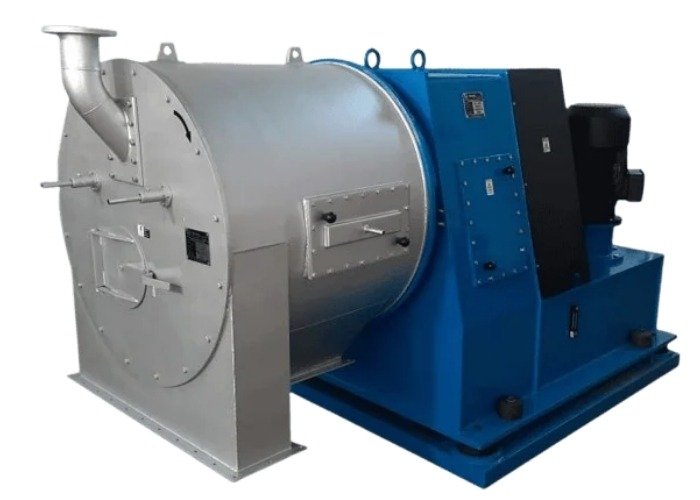
Hydraulic Pusher Centrifuge Enquiry
Key Features of Hydraulic Pusher Centrifuge
The hydraulic system provides controlled reciprocating movement for continuous cake transport and reliable solids discharge.
Hydraulic Power Pack
Supplies pressurized oil to operate the reciprocating pusher mechanism.
Reciprocating Pusher
Creates controlled forward and return movement for continuous cake transfer.
Pressure Control
Hydraulic pressure can be regulated according to machine and process requirements.
Oil Filtration
Hydraulic filtration helps protect pumps, valves, seals and moving components.
Oil Cooling
Cooling arrangements may be used to maintain hydraulic oil temperature during continuous operation.
Serviceable Components
Pumps, valves, filters, seals and gauges can be serviced or replaced as required.
Hydraulic Drive System of Pusher Centrifuge
The hydraulic system produces the linear movement required for the pusher assembly while the rotor drive separately rotates the basket.
The hydraulic drive system is one of the most important operating systems in a Pusher Centrifuge.
While the main rotor drive generates the rotational speed required for centrifugal separation, the hydraulic system performs a different function by producing controlled reciprocating movement.
Hydraulic oil flow is directed through the circuit to operate the pusher actuator, which moves the separated cake progressively toward the discharge end of the machine.
How the Hydraulic Pushing Mechanism Works
Hydraulic flow is converted into controlled forward and return motion of the pusher assembly.
Cake Formation
Solids accumulate on the filtration screen and form a cake inside the rotating basket.
Hydraulic Forward Stroke
Pressurized hydraulic oil moves the pusher toward the solids discharge direction.
Cake Advancement
The pusher transfers a portion of the filter cake toward the discharge end.
Return Stroke
Hydraulic flow is redirected and the pusher returns before the next pushing cycle.
Reciprocating Pusher Movement
The pusher performs controlled axial movement rather than rotating independently with the basket.
Forward Stroke
Hydraulic force moves the pusher plate or pusher assembly in the discharge direction, advancing the formed cake.
Return Stroke
Hydraulic oil flow is redirected and the pusher returns to its starting position while fresh solids continue forming.
Stroke Length
Stroke length represents the axial travel of the pusher during one reciprocating movement and depends on machine design.
Stroke Frequency
The pushing frequency depends on feed rate, cake formation, basket dimensions and product behaviour.
Main Components of Hydraulic Power Pack
The hydraulic power pack generates, controls and distributes hydraulic oil flow to the pusher mechanism.
Hydraulic Motor
Provides mechanical power required to drive the hydraulic pump.
Hydraulic Pump
Converts motor power into hydraulic oil flow for pusher operation.
Oil Reservoir
Stores the hydraulic oil used throughout the operating circuit.
Directional Valve
Controls oil flow direction for forward and return pusher movement.
Pressure Control Valve
Regulates or limits hydraulic system pressure during machine operation.
Hydraulic Filter
Removes contamination from oil to protect hydraulic system components.
Hydraulic Pressure & Stroke Control
Hydraulic pressure determines the pushing force available for controlled cake movement.
The required hydraulic pressure can vary according to machine model, cake resistance, product characteristics, basket dimensions and pusher design.
Excessive pressure can increase mechanical and hydraulic stress, while insufficient pressure may cause irregular or incomplete cake movement.
The exact hydraulic operating pressure, stroke length and stroke frequency should therefore be specified according to the selected machine model and verified engineering data.
Hydraulic Motor Specifications by Model
Hydraulic motor ratings vary according to machine size and selected centrifuge configuration.
| Model | Basket Diameter | Hydraulic Motor | Rotor Motor |
|---|---|---|---|
| HT-250 | 275 mm | 5 HP | 7.5 HP |
| HT-350 | 375 mm | 7.5 HP | 10 HP |
| HT-450 | 475 mm | 10 HP | 15 HP |
| HT-550 | 575 mm | 15 HP | 25 HP |
| HT-650 | 675 mm | 20 HP | 30 HP |
| HT-750 | 755 mm | 25 HP | 40 HP |
| HT-850 | 855 mm | 30 HP | 60 HP |
| HT-950 | 955 mm | 40 HP | 60 HP |
| HT-1050 | 1055 mm | 50 HP | 70 HP |
Hydraulic Oil, Filtration & Cooling
Clean hydraulic oil and correct operating temperature are essential for reliable hydraulic system performance.
Hydraulic Oil Selection
Oil grade should match hydraulic system design, pump recommendation and operating temperature.
Oil Filtration
Proper filtration helps prevent contamination from affecting pumps, valves and seals.
Oil Cooling
Cooling may be required during continuous duty to maintain suitable oil temperature and viscosity.
Common Hydraulic Maintenance Requirements
Routine inspection helps reduce hydraulic system problems and unplanned machine downtime.
Oil Level & Condition
Inspect hydraulic oil level, cleanliness and operating condition.
Filter Inspection
Check suction and return filters according to maintenance intervals.
Pressure Monitoring
Monitor hydraulic pressure and investigate abnormal pressure changes.
Temperature Monitoring
Check hydraulic oil temperature during continuous machine operation.
Hose & Seal Check
Inspect hoses, fittings, joints and seals for leakage or wear.
Pusher Movement
Verify smooth forward and return stroke operation during service.
Common Hydraulic Problems & Checks
Slow Pusher Movement
Check hydraulic pressure, oil level, filter condition, pump performance and valve adjustment.
Pusher Does Not Move
Inspect hydraulic motor, pump, directional valve, oil supply and actuator condition.
Irregular Pusher Movement
Check for air in the circuit, unstable pressure, contaminated oil or restricted oil flow.
High Oil Temperature
Inspect oil level, filters, operating pressure, cooling arrangement and oil viscosity.
Hydraulic Pusher Centrifuge Replacement Components
Spare parts can be supplied according to machine model and existing hydraulic component details.
Hydraulic Pump
Replacement pump according to machine and hydraulic system specification.
Hydraulic Motor
Motor selection according to HT-series machine configuration.
Control Valves
Directional and pressure control valves for hydraulic circuit service.
Hydraulic Seals
Replacement sealing components for hydraulic moving assemblies.
Oil Filters
Replacement filtration components for hydraulic oil cleanliness.
Pressure Gauges
Pressure monitoring components for hydraulic system inspection.
Hydraulic Pusher Centrifuge Manufacturer in India
Shreeji Engineers manufactures Hydraulic Pusher Centrifuge systems and replacement components for industrial solid-liquid separation applications.
Hydraulic Pusher Centrifuge Frequently Asked Questions
1. What is a Hydraulic Pusher Centrifuge?
A Hydraulic Pusher Centrifuge is a continuous filtration centrifuge in which a hydraulically operated reciprocating mechanism moves the separated filter cake through the basket.
2. What is the purpose of the hydraulic system?
The hydraulic system provides the pressure and oil flow required to create forward and return pusher movement.
3. Does the hydraulic system rotate the basket?
No. The rotor drive rotates the basket, while the hydraulic system creates axial reciprocating movement of the pusher.
4. Can hydraulic pressure be adjusted?
Hydraulic pressure can be controlled according to machine design and application requirements. The correct operating range should follow the machine specification.
5. What hydraulic maintenance is required?
Routine maintenance includes inspection of hydraulic oil, filters, hoses, seals, operating pressure, oil temperature, valves and pusher movement.
6. Why is hydraulic oil filtration important?
Proper filtration helps protect pumps, valves, seals and actuators from contamination-related wear and malfunction.
Explore Our Pusher Centrifuge Range
Need a Hydraulic Pusher Centrifuge?
Share your product name, required capacity, feed concentration, crystal size and operating conditions with Shreeji Engineers. Our team can help you select a suitable Hydraulic Pusher Centrifuge model and hydraulic configuration.

 Users Today : 9
 Users This Month : 170
 Total Users : 1078